Yet another project from

Data files: The Patterson format
The P2Reader functions P2Reader:read_patterson_file and P2Reader:write_patterson make use of the Patterson format to represent an activity-on-the-node network with renewable resource use. The format is a simple text file and its structure is explained on the illustrative project network of figure 1. Each node above the node is assumed to be the activity duration. More information on activity-on-the-node networks can be found at “Project networks: Nodes and arcs or arcs and nodes?”.
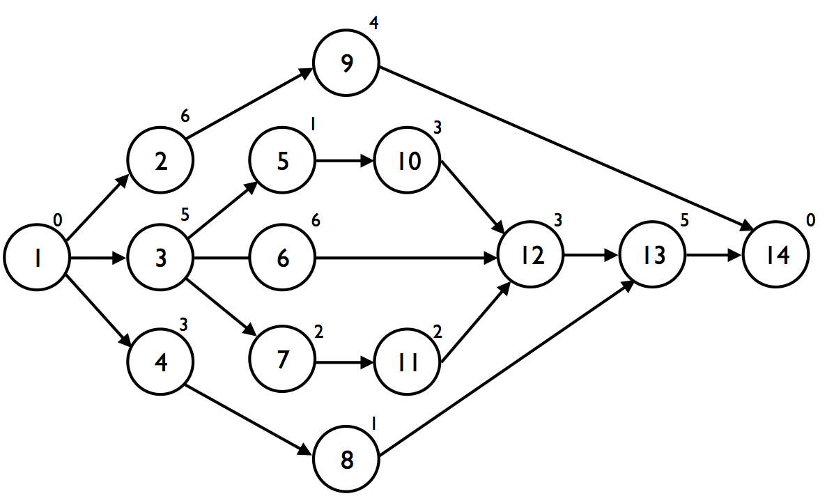
Figure 1. An illustrative activity-on-the-node network
(Source: Figure 7.1 and Table 7.2 of “Project Management with Dynamic Scheduling: Baseline Scheduling, Risk Analysis and Project Control")
The network of figure 1 has two dummy activities, i.e. dummy start node 1 and dummy end node 14, and hence, the network contains 14 activities in total, dummies inclusive. The Patterson format also makes use of start and end dummy nodes and is structured as follows:
Line 1:
- Number of activities (starting with node 1 and two dummy nodes inclusive)
- Number of renewable resources
Line 2: (one number for each resource)
- Availability for each renewable resource
Next lines from (one line for each activity, starting with a dummy start activity and ending with a dummy end activity)
- Activity duration
- Resource requirements for each resource type
- Number of successors
- Activity ID for each successor
It is assumed that the project network of figure 1 needs four renewable resource types. Consequently, the Patterson text file for the network of the figure is as follows:
14    4
10    20    8     10
0     0     0     0     0     3     2     3     4
6     7     15    2     6     1     9
5     1     8     4     8     3     5     6     7
3     5     8     3     3     1     8
1     6     15    2     6     1     10
6     1     13    0     3     1     12
2     2     16    2     0     1     11
1     2     9     4     4     1     13
4     8     12    5     5     1     14
3     6     17    5     0     1     12
2     2     10    2     5     1     12
3     6     5     5     4     1     13
5     8     10    3     7     1     14
0     0     0     0     0     0
As an example, activity 2 of figure 1 needs 7, 15, 2 and 6 units of resource 1, 2, 3 and 4, respectively. The availability of these resources is set at maximum 10, 20, 8 and 10 units.
Note that P2Reader will not read the start dummy activity 1 and end dummy activity 14 and hence the number of activities (dummies exclusive) will be equal to 12. Therefore, the IDs of the activities will start from 1 and end at 12 and the P2Reader object will see the project network as displayed in figure 2. Activities 1, 2 and 3 are start activities (no predecessors), and activities 7, 8 and 12 end activities (no successors).
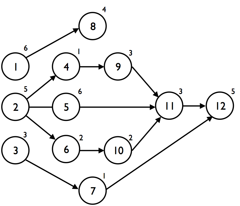
Figure 2. The activity-on-the-node network of figure 1 in the P2Engine (using P2Reader class)
You can download C++ code to read Patterson files with static and dynamic use of memory.